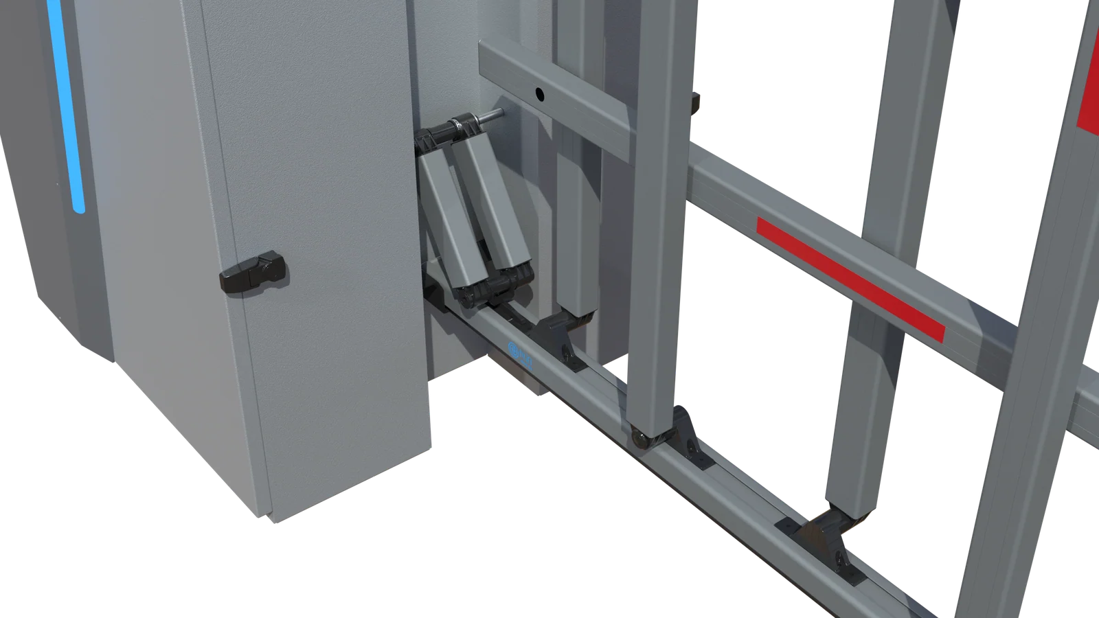
Cabinet-to-fence connection
Original manufacturer artwork shows the connection between the cabinet and the articulated fence.

VEHICLE ACCESS
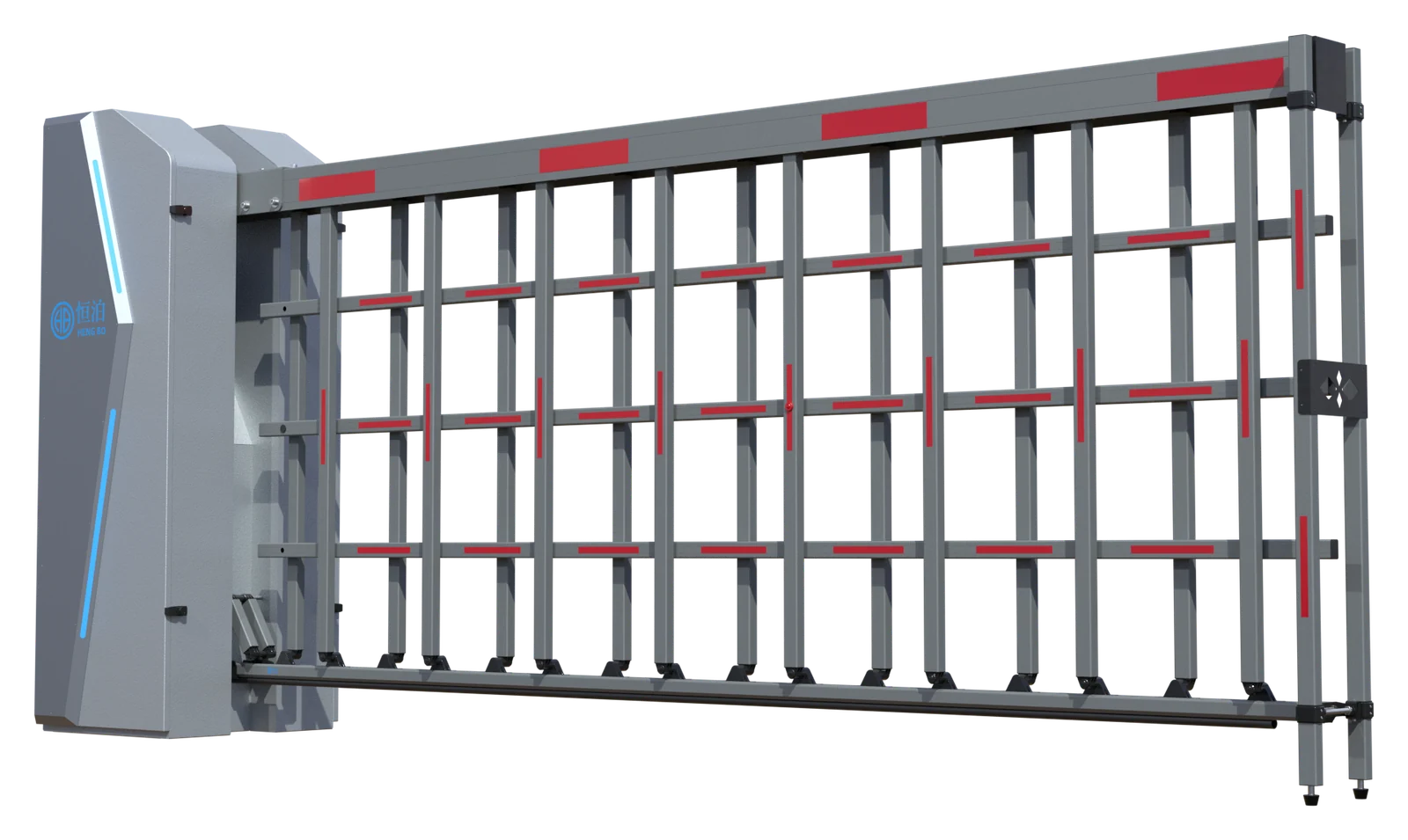
A folding fence-arm barrier with a faceted silver cabinet, blue lighting details and red reflective markings. The articulated fence assembly changes position as the arm opens.
LINKED FENCE MOVEMENT
The linked rails and uprights change their arrangement as the fence is raised. Treat the complete assembly as the moving object when planning the entrance.
Check the lane opening, end-support position and the cabinet area together.
Keep the travel of every rail and linked upright clear. Original raised and closed views below show the arrangement.
Confirm headroom, cable entry, servicing access and the selected controls against the final installation drawing.
STRUCTURE & DETAILS
The faceted cabinet carries a connected fence assembly with multiple rails and upright links. Separate original closed and raised views show how its overall arrangement changes.
Original manufacturer artwork shows the connection between the cabinet and the articulated fence.
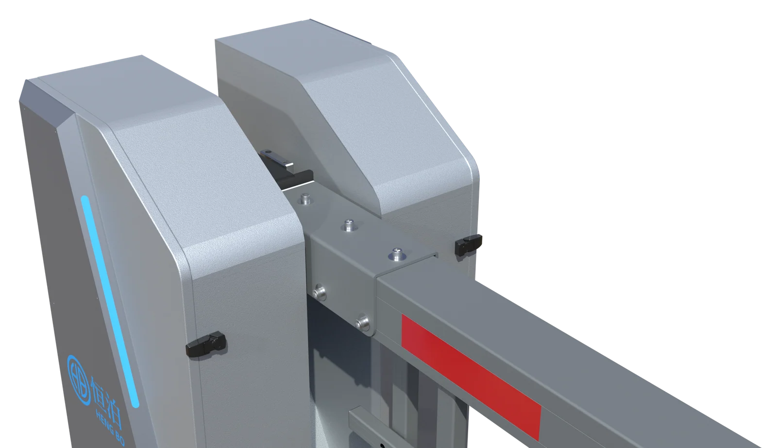
The upper joint connects the fence assembly to the cabinet.
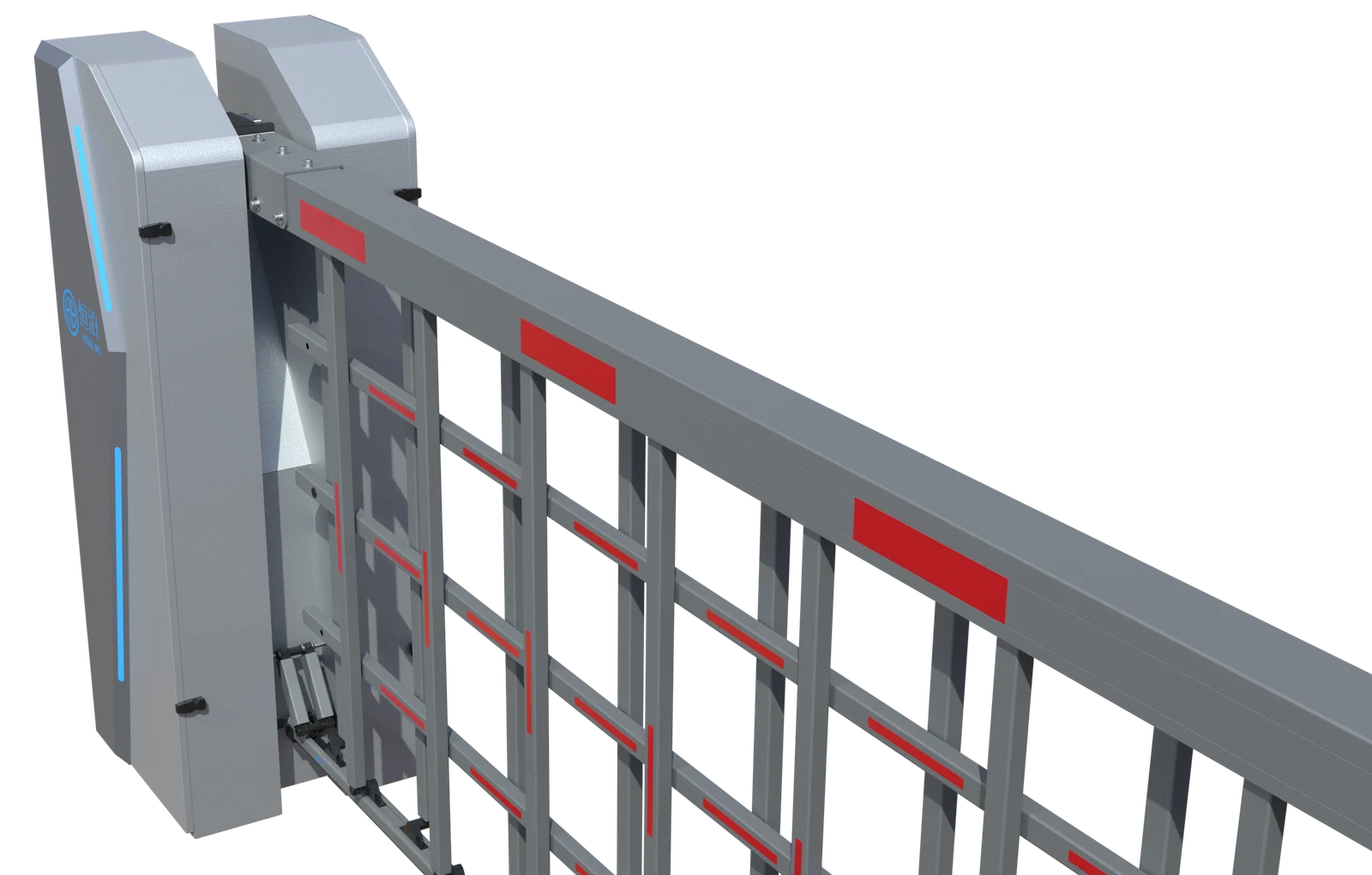
The close-up shows the upper rail, upright members and their connections.
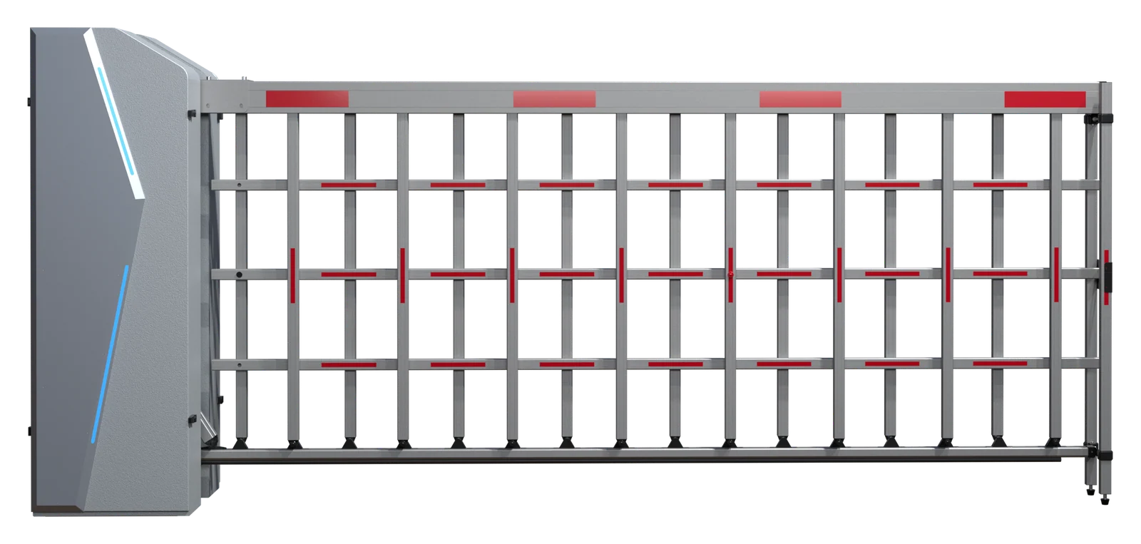
A front view shows the cabinet and fence together.
OPERATING POSITIONS
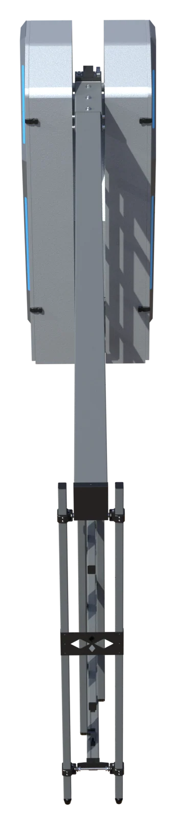
Original manufacturer artwork shows the fence in two positions. Movement space and installation clearances depend on the final configuration.
ENTRANCE PLANNING
Consider the full arm and linkage movement, available headroom and the end-support position. Installation dimensions are confirmed for the selected configuration.
Build a complete systemMODEL SPECIFICATIONS
| Parameter | Specification |
|---|---|
| Model | DZ-60 |
| Barrier type | Vertical fence |
| Configuration shown | Grey-white cabinet and fence arm |
The quotation confirms the supplied equipment and configuration.
PRODUCT QUESTIONS
It uses an articulated fence assembly with multiple horizontal members and vertical links. The assembly changes its shape and position as it is raised beside the cabinet.
They are original manufacturer product views of the two positions. They help show the arrangement; final travel, support and installation details are confirmed for the supplied equipment.
Check the full fence and linkage movement, overhead clearance, the cabinet area and the end support. Share the clear opening and surrounding obstacles in a plan or site photographs.
The product views show the grey-white cabinet with blue accents and the matching fence assembly. Confirm the required finish and configuration in the enquiry.
YOUR PROJECT
Share the equipment quantity, destination country and site requirements.